Seclusion (or Time-Out) Rooms
Seclusion rooms (AKA time-out rooms) are rooms within a school or other facility reserved for separating an individual from the rest of the population for behavioral reasons. Regulations for time-out rooms vary widely from state to state and jurisdiction to jurisdiction. Before researching seclusion/time-out locks be sure to familiarize yourself with the regulations in your jurisdiction.
Time-Out Room Principals and Procedures
The main principal guiding the function of locking hardware for time-out rooms is that they remain unlocked at all times except when the room is in use, and when in use, physically held in a temporarily locked position by a staff member. In other words, a staff member must hold the lock in the locked position the entire time the individual is in seclusion. Should the staff member take their hand off the lock, the lock will automatically be unlocked.
According to most regulations, it is the duty of the staff members administering seclusion to ensure the safety of the person being secluded by observing them constantly during the seclusion period. The nature of time-out room locking devices helps ensure that observation is done by requiring the staff member to manually keep the door locked the whole time.
Once again, time-out rooms are highly controversial and subject to regulations. Before creating a time-out room, be sure to check with the local building inspector, fire marshal, and/or superintendent of schools within the jurisdiction.

Corbin Russwin CLX3320TO Time-Out lock
The Corbin Russwin CLX3320TO Time-Out lock (above) has levers on both sides. The inside lever is unlocked until a staff member depresses the button on the outside lever. As long as the staff member keeps the button depressed the inside lever will remain locked. The moment the staff member releases the button the inside lever becomes unlocked.
This lock would be used in applications where the lock is not subject to a lot of abuse. The inside lever is vulnerable to attack, and neither lever is anti-ligature.


ABH 6830 Time Out Lock
The ABH time-out function hospital push/pull (above) works in reverse action, that is, the latch remains retracted until the paddle is pushed down or up, depending on inswing or outswing application.
Since it is a tubular hospital latch with a robust paddle mechanism, it is a durable lock. And since it has only a blank plate on the interior side it has little vulnerability and could be considered to be anti-ligature from that side.

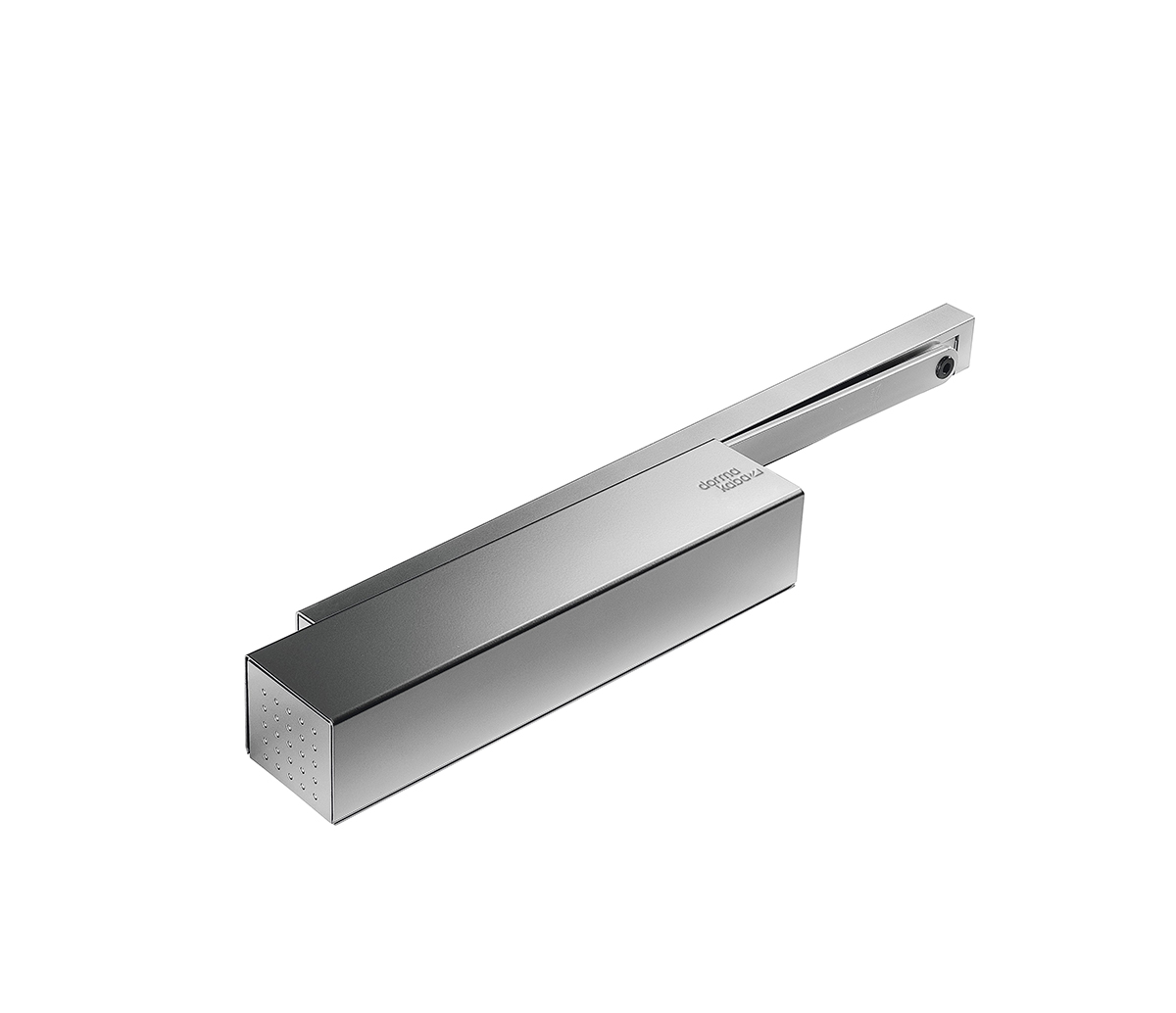
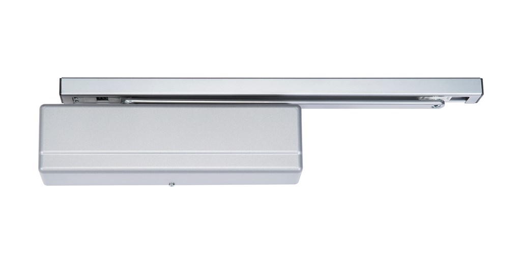
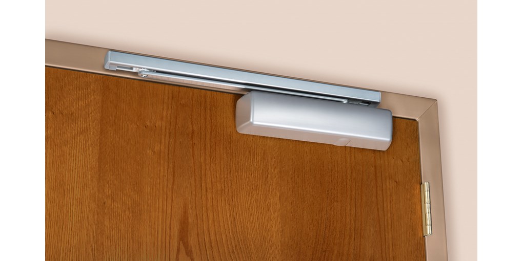
Dormakaba Best Access SSR Series Time-Out Lock
The Dormakaba SRR series of seclusion locks (see above) offer robust resistance to forcible exit. The time-out function is actuated by the staff member constantly pressing down on the lever. The moment the staff member removes their hand from the lever the latches are released.
A single point version is also available as well as the 3-point version above. Both the 3-point and the single point have inswing and outswing versions.
Since the SSR lock is surface applied to the exterior side of the door it could be considered to be anti-ligature from that side.

Accurate Hardware 9044TO | 9144TO Time-Out Lock
As of this writing, I believe this is the only time-out function mortise lock available.
The Accurate Hardware model 9044TO | 9144TO time-out mortise lock (pictured above) is made to order and customizable at the factory. It is available with anti-ligature handles on both sides, an anti-ligature handle on the exterior and blank plate on the interior side and in other configurations as well.

Vertical Double Magnet Housing with M62 or M82 electromagnetic locks
Yes, it is possible to use electromagnetic locks on a time-out room application, and it makes sense. Electromagnetic locks are inherently fail safe.
To make an electromagnetic locking system, use a full height vertical housing as shown above, and install two M82 mag locks in the housing. This will provide 3600 pounds of holding force. The housing must fit perfectly from threshold (or floor) to header and must not extend past the reveal of the door frame to avoid creating a ligature point on the inside of the room.
On the door frame on the outside of the time-out room door, install a momentary contact, normally open pushbutton switch. Now the magnets will only be locked while the button is pressed. As soon as the staff member takes their hand off the button, the door will be unlocked.
Whenever creating a seclusion or time-out room be sure to consult with your local authorities before proceeding.