You are currently browsing the archives for the access control category


Multi-function Doorways, Part One

As seen in Doors and Hardware Magazine.

Whenever something is invented, humans find more uses for it.  This is certainly true for door automation and electric locking.  It was not long after people realized a door could be unlocked remotely using an electric strike and a door could be opened automatically using a power operator (automatic door opener) that they began using these devices together.   Of course this combination of devices was soon interfaced with intercoms.  Exit devices with electric latch retraction and electromagnetic locks were thrown into the mix, as well as access control, delayed egress and/or security interlock systems.  Any of these systems alone is sufficient to complicate an installation, but when you start to use several on one opening, that’s when things really start to get interesting.

A hospital can be one of the best places to run into a doorway that needs to perform many functions (pun intended).  Hospitals seem to have more varied reasons to keep different people out at different times, or to let them in or out by different means.  In addition to standard life safety and security issues, hospitals also have to anticipate the needs of patients who may be under the influence of medication and/or mental disorders and/or have physical limitations.  Some patients must be kept inside for their own safety while all patients must be able to exit swiftly and safely in the event of a fire.

Let’s use as an example a hospital emergency ward entrance used primarily by ambulance drivers.  The hospital wants only ambulance personnel and the security guard  to be able to activate the power operator, and to control access by use of a remote switch operated by the security guard  for the general public and an access code by hospital employees (other than ambulance personnel).

Since it is a pair of doors, concealed vertical rod exit devices are the most efficient, safe and secure way to lock them and provide reliable free egress in the event of an emergency.  However, since there is a power operator involved, these devices must be equipped with electric latch retraction; and since use of the power operator was to be limited, a second electric means of opening the door would be required.

A simple way to solve the problem of the second means of unlocking is by using electrified exit device lever trim with one of the concealed vertical rod exit devices.  Persons not requiring the power operator can get in by using the access control, or the security guard  can “buzz” them in using one of two remote buttons.  Because there will be two means of unlocking the door electrically, the security guard  will need a small desk unit with two buttons:  one that activates the power operator and electric latch retraction and one that activates the electric exit device trim.

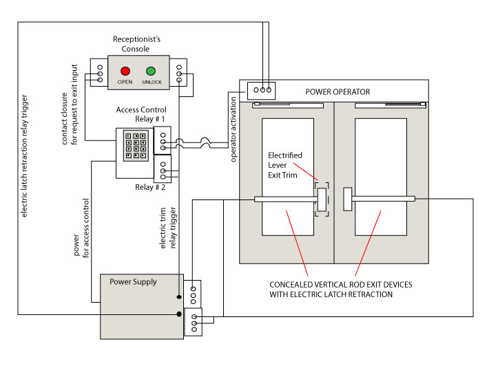
Below is an amateur wiring diagram (made by me) of how, basically, the system works.

Central to the concept is an access control device with two relays and a request to exit input.  This allows several of the connections to be made through the access control system.  If the access control system on site does not provide more than one relay, the same functions can be accomplished by using additional relays in the power supply.

The system as shown in my illustration above works like this:

Ambulance personnel activate the power operator using the access control system.  The access control system signals the power operator via contact closure in Relay #1.  The power operator triggers the relay in the power supply to retract the latches of the exit devices, then opens the door.

Other authorized hospital personnel use the access control system to unlock the lever trim.  The access control system changes the state of Relay #2, triggering the relay in the power supply to unlock the trim.  They turn the lever, pull the door open and walk in.

Injured people arrive on foot at the Emergency Room entrance.  The Security Guard sees them (or is notified by intercom, not shown) and lets them in by pressing the red button, activating the power operator, or by pressing the green button that unlocks the exit device trim.

There exist many possible variations of this system.  Knowledge of access control systems and door hardware are required, but the most important principal in play is the use of contact closure to signal multiple devices.
The Elusive “Touch Chip” Credential

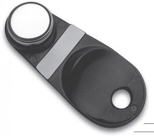
A few years ago, Ingersoll Rand (IR) purchased Locknetics Security Engineering in Connecticut, and since then gradually rebranded the line as Schlage Electronics.   A little over a year ago, as part of the process of closing the Connecticut facility, Schlage Electronics started phasing out its TR80 and TR81 touch readers.  These readers were based on the old technology of the Dallas chip, otherwise known IR/Locknetics land as the touch chip or iButton.  By the end of 2010, Schlage phased out all commercial electronic locking products that incorporated touch chip readers, such as touch readers and locking technologies that incorporated the touch reader, such as the CM line of computer managed locks and their electromagnetic locks with on-board access control.

When the new price books were released in January 2011, the touch chip credential was completely absent.   When questioned about legacy systems, representatives from IR indicated that touch chip users should migrate over to prox tags.  With the new AD and CO series electronic locks, Schlage made available new software and a new hand held programmer (the HHD-KIT) that is backwards compatible with the old hardware.  They also produced a tag with a prox chip on one side and a touch chip on the other so that legacy facilities would be able to carry both credentials over the period of years during which the old CM or other series locks would age out of the system.

One might think that the touch chip has completely faded from the Schlage Electronics scene, but such is not the case.  Looking through the Multi-Family Price Book what do I discover but the new SRT-100 touch reader and a barrage of “iButton” touch chip credentials such as the one pictured.   The new CT-5000 controller that replaces the old CT-1000 controller is also available for those who need to replace ailing legacy systems.  It is my understanding that the iButtons that appear under the multi-family division are fully compatible with legacy technologies such as CM locks or KC-2 series locks.

There is also a new line of smart residential locks that incorporate touch chip technology.  So it is safe to say that touch chip technology is not going to disappear anytime soon.  So if you have a large facility full of old Locknetics products that take iButtons, don’t panic.  At least for now you can still get them.


New PS914RFK Retro-fit Kit from Von Duprin

According to IR tech support, the PS914RFK is a bracket and main board assembly designed to install into existing PS873 enclosures.  The idea is to ease PS873 replacement and it looks to me like it will accomplish that.

In addition to the PS873, you will need to replace all existing option boards that are present.

  • To replace 871-2, use 900-2RS
  • To replace 873-BB, use 900-BBK if you need batteries included.  If not, use 900-BB for the board only
  • To replace 873-FA, use 900-FA
  • To replace 873-4TD, 873-AO, or 873-SI, use 900-4RL
  • To replace 873-2Q, use 900-2Q

The following boards have been discontinued:

  • 873-AL
  • 873-AC
  • 873-DE

In several pieces of Ingersoll Rand literature I have seen the 900-BB board depicted as if it includes batteries.  It does not.  So if you want your battery kit to come with batteries, you need to get the 900-BBK.


PS900 Series Schlage Electronics and Von Duprin Power Supplies Demystified

Von Duprin and Schlage Electronics are divisions of Ingersoll Rand. Both are major manufacturers of power supplies for use with electric locking systems and access control. As of January 1st, 2011, Ingersoll Rand discontinued two of their power supply product lines, the PS800 series Von Duprin and the Schlage Electronics 500 series, and merged them into the new PS900 series.

A split in power supply branding may or may not remain, depending on what document you are looking at, but whether they say they are Schlage or Von Duprin, they are all the same PS900 series.

Here is the lineup:

PS902 – 2 Amp output at 12 or 24VDC, field selectable

Compatible with these option boards:

  • 900-BBK: Battery Backup – back up power in case of power outage, includes batteries
  • 900-FA: Fire Alarm – relay for interface with fire alarm panel  – wires to main board
  • 900-2Q: 2 Relay QEL control Board – to run 2 Von Duprin QEL devices
  • 900-4R: 4 Relay Output Board – four relay outputs to operate 4 electric locking devices, not QEL or EL
  • 900-4RL: 4 Relay Logic Board – for man trap or security interlock systems or up to 4 QEL devices
  • 900-8F: Fused 8 Zone Distribution Board – 8 outputs, fused for circuit protection
  • 900-8P: PTC 8 Zone Distribution Board – 8 outputs, circuit breaker protected

PS902 can accommodate 1 of the above option boards in addition to the 900-FA option and battery backup.

For use with electric locks and with Von Duprin Quiet Electric Latch retraction (QEL) exit devices, but NOT with Von Duprin electric latch retraction (EL) exit devices.

PS904 – 4 Amp output at 12 or 24VDC, field selectable

Compatible with these option boards:

  • 900-BBK: Battery Backup – back up power in case of power outage, includes batteries
  • 900-FA: Fire Alarm – relay for interface with fire alarm panel  – wires to main board
  • 900-2Q: 2 Relay QEL control Board – to run 2 Von Duprin QEL devices
  • 900-4R: 4 Relay Output Board – four relay outputs to operate 4 electric locking devices, not QEL or EL
  • 900-4RL: 4 Relay Logic Board – for man trap or security interlock systems
  • 900-8F: Fused 8 Zone Distribution Board – 8 outputs, fused for circuit protection
  • 900-8P: PTC 8 Zone Distribution Board – 8 outputs, circuit breaker protected

PS904 can accommodate up to 2 option boards and battery back up.

Note:  no plug-in for fire alarm relay on main board.  900-FA is only usable with the PS904 if used with an option board.

For use with electric locks and with Von Duprin Quiet Electric Latch retraction (QEL) exit devices, but NOT with Von Duprin electric latch retraction (EL) exit devices.

PS906 – 6 Amp output at 12 or 24VDC, field selectable

Compatible with these option boards:

  • 900-BBK: Battery Backup – back up power in case of power outage, includes batteries
  • 900-FA: Fire Alarm – relay for interface with fire alarm panel  – wires to main board
  • 900-2Q: 2 Relay QEL control Board – to run 2 Von Duprin QEL devices
  • 900-2RS: 2 Relay EL Control Board – to run up to 2 Von Duprin EL devices
  • 900-4R: 4 Relay Output Board – four relay outputs to operate 4 electric locking devices, not QEL or EL
  • 900-4RL: 4 Relay Logic Board – for man trap or security interlock systems
  • 900-8F: Fused 8 Zone Distribution Board – 8 outputs, fused for circuit protection
  • 900-8P: PTC 8 Zone Distribution Board – 8 outputs, circuit breaker protected

PS906 can accommodate up to 3 option boards, fire alarm interface (with option board) and battery back up.

For use with electric locks and with up to 6 Von Duprin Quiet Electric Latch retraction (QEL) exit devices, but NOT with Von Duprin electric latch retraction (EL) exit devices.

PS914 – 4 Amp output at 12 or 24VDC, field selectable

Compatible with these option boards:

  • 900-BBK: Battery Backup – back up power in case of power outage, includes batteries
  • 900-FA: Fire Alarm – relay for interface with fire alarm panel  – wires to main board
  • 900-2Q: 2 Relay QEL control Board – to run 2 Von Duprin QEL devices
  • 900-2RS: 2 Relay EL control Board – to run up to 2 Von Duprin EL devices
  • 900-4R: 4 Relay Output Board – four relay outputs to operate 4 electric locking devices, not QEL or EL
  • 900-4RL: 4 Relay Logic Board – for man trap or security interlock systems
  • 900-8F: Fused 8 Zone Distribution Board – 8 outputs, fused for circuit protection
  • 900-8P: PTC 8 Zone Distribution Board – 8 outputs, circuit breaker protected

PS914 can accommodate 2 of the above option boards, plus fire alarm interface (on one of the boards) and battery back up.

Capable of powering:

  • Up to 4 Electric Latch retraction (EL) exit devices with 900-4RL board
  • Up to 2 EL devices with 900-2RS board
  • Up to 4 Quiet Electric Latch retraction (QEL) exit devices
  • Up to 4 Chexit (CX) delayed egress exit devices off the main board (use 900-8FA combination board if Fire Alarm relay is required)
  • Electric locks or strikes


Ordering Tips:

PS-914 is a 4 Amp power supply that is double the capacity of the old PS873, however, from my conversation with IR tech support, their feeling is that it is prudent to power no more than 4 EL devices per PS-914.  Theoretically the power supply could support as many as 8 EL devices however this presents the challenge of timing the relays so that no two can change states at the same time.  If two EL devices are powered up simultaneously the PS-914 could be damaged.

None of the PS900 series power supplies are a drop-in replacement for their predecessors, and the old and new option boards are not cross-compatible with the old and new power supplies.  Therefore, replacing old power supplies with new can present a rewiring challenge.

Ordering back-up batteries can be a little tricky, since they have very similar part numbers for the batteries, the charging circuit board, and a set that includes the board and the batteries.

  • 900-BAT – Pair of batteries only
  • 900-BB – Battery back up board only
  • 900-BBK – Power battery back up kit, board and batteries


Glass Door Electric Locking Solutions

Installing an electric locking system on an existing, currently unsecured all-glass or Herculite door can be a challenge for the security professional, but there are solutions.  Here are a few:

Electromagnetic Locks

Securitron Glass Door Solution

The Securitron solution to the glass door locking problem is… glue.   When I sell this solution, I usually use:

  • M62G (1200 lb. holding force electromagnetic lock with conduit fitting)
  • AKG (adhesive kit for glass doors)
  • GDB (glass door bracket for armature)

For all glass doors with all glass headers, I also use the HEB-G header extension bracket.  This can also be glued in place using the Securitron AKG.  Since the AKG includes enough glue to do 10 glass-door mag installs, there is more than enough to do one all-glass door and one all-glass header.

Everybody Else’s Mag-Lock-for-Glass-Door Solution

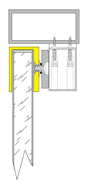
As far as I know, no one besides Securitron really deals with the situation of an all glass header.  For all-glass doors, all the other companies that make electromagnetic locks use variations of the HDB, or Herculite Door Bracket.  This bracket is a U-channel that slides down over the top of the door.  It’s a clip-on system:

Illustration from Rutherford Controls web site

The Herculite door bracket concept seems to work well except in cases were there is a reduced gap between the top of the door and the header.  In that case the U-channel idea is out because the HDB bracket will keep the door from closing.  Then it’s the Securitron and the glue or something else altogether.

RCI Cushion-Lok

A pricey but classy and easy to install alternative to the electromagnetic solution is the Rutherford Controls Cushion-Lok.  The Cushion-Lok is a specially constructed, fail safe electric strike and passive latch that gently locks the door upon closure.   Shown below is the RCI 3360 which is pre-installed on patch fittings that slide onto the glass of the door and “frame” when the entire doorway – door, lintels and header – is made of glass.

Not shown is another version for use with a wood or metal frame and Herculite door.

It is worthwhile to note that the reason security professionals are faced with installing electric locks on existing all-glass doors is because of a lack of planning on the part of the architect or project manager.  It is much easier for a glass door manufacturer to pre-install a locking system than it is for a security professional to install it after the fact.

Locking People In

I often get a request to help create a system that locks people in.  People want to lock children inside a daycare center, students inside a “Time-Out” room, babies inside a nursery in a maternity hospital or patients inside, for example, an Alzheimer’s disease in-patient facility for their own good.

“Well, what if there’s a fire?” I ask.

That’s really the issue.  If we are keeping them in, how are they supposed to get out in the event of a fire?  Yet, except when there is a fire or other emergency that renders the building unsafe, it is in their best interest if they are kept inside.

Often, people simply want to lock people in with an electromagnetic lock or other device.  Since this is certainly a violation of life safety code, any injury that may result would be uninsurable and could invite litigation.

I discuss delayed egress systems in depth in another article (click here to read).     A delayed egress system is really the right way to do this, since it is actually covered in the NFPA 101A Special Locking Arrangements section of the fire safety code, but it is fairly inconvenient to use.  To get out without setting off an alarm users must use some kind of bypass request to exit switch like a keypad, card reader or key switch – much less convenient than, say, simply pushing a door open via the push pad on an exit device.

The gist of a delayed egress system is that, after a short ‘nuisance’ delay, the lock sounds an alarm for fifteen seconds and then lets the person out.  That means that authorities on the secured premises have fifteen seconds to get to the exit and prevent unauthorized egress.

Where unauthorized egress is not a life threatening prospect, therefore, a delayed egress system is perfectly adequate.  However, when a person’s life may depend on being kept inside their care facility, a more complex solution maybe required.

A great solution for Alzheimer’s or other dementia care facilities is the WanderGuard system by Stanley.  This system is designed for Alzheimer’s and other health care facilities where unscheduled patient departure is an issue, and covers other needs with fall monitoring and patient call capabilities.  Patients are fitted with bracelets that serve as tracking and communication devices.  As one might expect, such a system is not inexpensive and a bit on the overkill side for use in a day care center or maternity facility.  To physically keep people inside the facility, the WanderGuard system is designed to interface with delayed egress locks.

I think that the WanderGuard system would be a good choice for use in maternity ward nurseries as well.

The situation is more challenging when you have a day care center or a “Time-Out” room.

I had heard that Schlage was coming out with a mechanical time out lock, but a search as of today renders only the same Time-Out Room solution:  An electromagnetic lock with a momentary pushbutton.  The troublesome child is forced into a room, the door is shut, and then the teacher or other disciplinarian must physically press the momentary contact pushbutton to keep the magnetic locked locked.  As soon as the teacher lets go, the child is free.

As long as the button is momentary, I have no problem with this idea.  Should there be a fire or other life safety emergency, even if the teacher panics and runs away, leaving the child in the Time Out Room, the child will still be able to leave the room and exit the building.

The right way to prevent the kids in a daycare center from running out of the building and into the street without permission is with a delayed egress system.  True, it may be cumbersome to punch in a code on a keypad or present a proximity card for authorized egress, but delayed egress systems can be easily deactivated for periods of time, say, for drop off and pick up.  A delayed egress system is more expensive than, for example, an electromagnetic lock connected to the fire alarm system for safety.  But if you run the scenario of a fire in your mind, the fire alarm interface to the electromagnet malfunctions, panicked children and day care providers flinging themselves against an illegally locked door, too crazed with fear to think – suddenly a delayed egress system makes a lot more sense.

There is really only one place you can really lock someone in, and that’s in a jail or prison.  Otherwise there must be some provision to let them out – for safety’s sake.


Understanding Door Security Monitor Switches

A number of different kinds of switches are available to help you keep track of whether or not your door is shut and / or locked.  Here are some of them:

Door Status Monitor Switch

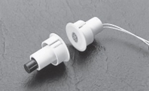
A door status monitor switch changes states when the door is opened or closed.  Typically this is accomplished by using a magnetic reed switch, either surface mounted or concealed in the edge of the door and door frame like the one shown at right.

How a Magnetic Reed Switch Works

The magnetic reed switch is typically installed on the door frame and the magnet that activates the switch is typically installed on the door.   Inside the magnetic reed switch, a thin piece of steel – a steel ‘reed’, if you will – is held in position by the attraction of the magnet when the door is closed.  When the door is opened, the magnet is taken away from the switch and the spring tension of the “reed” causes it to spring back against the other contact, changing the state of the switch.

Most magnetic reed switches are normally closed – “closed loop” – but are also available normally open (“open loop”) SPDT (single pole double throw, or “form C”) or DPDT (double pole double throw).

The Purpose of the Door Status Monitor Switch

The door status monitor switch is used to notify remote devices that a door is open or closed.  Typically these remote devices are burglar alarm panels or access control system controllers.   It does not tell you if the door is locked, just if it is closed.

Request to Exit Switch

The request to exit switch, also known as a REX switch, is so named because it is usually connected to the request to exit contacts on an alarm panel or access control board.  It is used to notify an external device that someone is exiting through, or wants to exit through, a door.  REX switches come in a wide variety of configurations, from push button palm switches engraved “push to exit” to switches concealed inside exit devices.  A motion exit sensor is also a form of request to exit switch.

Request to exit switches are available with a wide variety of contact configurations and with or without electronic or pneumatic time delay.   If the switch is being used as a means of egress for pedestrian traffic, it will need to comply with life safety code.  Life safety code varies from locality to locality as governed by your local AHJ – Authority Having Jurisdiction – that is, your local building inspector or fire marshal.

Latch Bolt Monitor Switch / Strike Monitor Switch

I write about Latch Bolt Monitor (LBM) switches and Strike Monitor Switches because they somewhat overlap.  Both are designed to monitor the position of the latch bolt.

Some LBM switches are inside locks and others are in electric strikes.  From inside the lock, they monitor whether the latch is extended or depressed.  When located in an electric strike, they monitor whether or not there is a latch bolt present in the keeper.

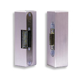
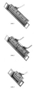
Pictured at right is Securitron’s line of inexpensive strike monitor switches as examples of strike monitor switches.  Several companies offer like products.  Strike monitor switches are an easy way to monitor if there is a latchbolt (or some other object) present in the keeper.   Several companies, such as Von Duprin, offer heavier duty monitor strikes.  Monitor strikes are sold as a finished unit that includes as strike and a switch whereas strike monitor switches are aftermarket add-on units.

Magnetic Bond Sensor / Bond Sensor

Magnetic bond sensor and bond sensor options refer to electromagnetic lock applications.  Many manufacturers offer Bond Sensor or Magnetic Bond Sensor as an option.  What this does is allow an electromagnetic lock to notify some external device that its holding force is below spec.  Authorities are alerted and the situation is addressed.

Maximizing Effectiveness

To maximize effectiveness of door monitor switches, it is best to use both a door status monitor and some kind of lock status monitor as well, and this is why:  because monitor switches can be fooled.  A door status switch will tell you if the door is open or closed – unless it has been altered to tell you the door is closed when it is not.  Also, a door may be closed, but not locked.  If you have a latch bolt monitor or magnetic bond sensor in place as well as a door status switch, you will know if the door is closed but not locked.

This is the center of this knowledge:  to know that the door is shut AND locked.


What’s Hot in Door Hardware

A couple of new innovative products have recently caught my attention.  Here they are:

Security Door Controls (SDC) Model LR100VDK:

Field Installed Electric Latch Retraction Retrofit Kit for Von Duprin Exit Devices


This product is available now.

http://www.sdcsecurity.com/whatsnew2.aspx#lr100

The mere 450mA inrush powering Security Door Controls’ new electric latch retraction retrofit kit is attractive enough.  Its compatibility with all Von Duprin touch bar style devices may make it just about irresistible.   Optional request to exit switch kits are available.  The unit is usable for access control and electric dogging applications.

The small inrush is huge.  (I always wanted to say that.)  High inrush electric latch retraction requires special, expensive power supplies.  Not so with the LR100VDK.  Your average regulated and filtered 1-amp 24vdc power supply will do nicely, thank you.

Another great aspect of this kit is that it is compatible with the Von Duprin 22 series exit device. So now, for relatively short money you can give a customer electric latch retraction in a decent quality exit device.

HES Model 8500 Electric Strike for Mortise Locks


http://www.hesinnovations.com/en/site/hesinnovations/Products-startpage/?groupId=141798&productId=764670

This product is due to become available by the end of August, 2011, but we’ll see.

Hanchett Entry Systems’ new lipless electric strike solution for mortise locks.

Installing an electric strike to release a mortise lock will be much easier with the HES 8500 since no cutting of the face of the frame is necessary.  Below is an illustration showing the difference between the HES 1006 standard electric strike for mortise lock and the new HES 8500.

HES 1006 prep for hollow metal

HES 8500 door prep for hollow metal - look ma, no lip!


This is not a new idea, but installers seem excited about the prospect of having an alternative to the Securitron UnLatch, which has been around for quite some time.  The Unlatch model that the HES 8500 will compete with will be the Securitron MUNL.

Of course, the advantage the MUNL currently enjoys is that, unlike the 8500, one can actually buy an MUNL.  Comparatively, the Securitron requires a door frame depth of about 1-7/8 inches whereas the the 8500 will require about 1-3/8 inches.  The 8500 will draw 240mA at 12 volts DC and 120mA at 24 volts DC and draws no inrush current.  The MUNL has an inrush of 2 amps at 24vdc or 4 amps at 12vdc and an operating current of 600mA at 12vdc or 300mA at 24vdc.  One important result of the lower current consumption of the 8500 will be that instead of the 4 amp 12vdc or 8 amp 24vdc power supply necessary for each MUNL, one 8 amp 24vdc power supply will theoretically power as many as perhaps 60 of the new HES 8500.  Of course then, factors like wire run will come into play, but still.

Another positive attribute will be that the 8500 will be field selectable for fail safe or fail secure whereas the MUNL requires an additional module to make it fail safe.

All in all, the 8500 seems that it will be a better choice all around.  We’ll just have to wait and see how it performs in the field after it becomes available at the end of August 2011.

Low Voltage Detective Work


Finding the Current Drop


As electric locking systems become increasingly complicated, troubleshooting these systems has also become more complex.  Yet certain basic principles always apply.

Case in point, a customer had access control on a stairwell door using a fire rated mortise exit device with an electrified mortise lock.  The solenoid in the mortise lock had burned out twice and the third one, newly installed, was already too hot to touch.  Granted, a solenoid operated fail safe device used in a continuous duty application will get warm, but it should not get too hot to touch.  So they called me to help them figure out what was going on.

To find the problem, I first listed the possibilities:

  1. They had gotten three defective solenoids in a row
  2. The power supplied is the wrong voltage – if the voltage was either too high or low, that would cause the solenoid to heat up
  3. The current supplied is inadequate – the solenoid used 330mA.  If it were being supplied with only 150mA, for example, the solenoid would heat up.

We determined that 27 volts DC was available at the door to power the 24 volts DC solenoid – perfectly acceptable – and we all felt that it was rather unlikely that they had received three defective solenoids in a row.  So that left current drop.  Where was the current going?  What was preventing it from getting the current it needed?

The access control tech on site could not determine whether the solenoid was getting enough current at the door by using a meter (for whatever reason) so we traced the current back through the line.

The power supply was a 6 amp, 24 volts DC power supply that had an output board with 8 fused outputs.  If all were in use, then a max of 750mA should be available from each output, provided they all were carrying the same amperage load.  We determined that four of the outputs were being used:  three were used to power electric strikes at 300mA and one was used to power the electric mortise exit device at 330mA.  The sum of the current draw for all devices attached to the power supply was therefore about 1.2 amps – well within the power supply’s capacity.  Therefore the power supply size was not the problem.  The technician measured the output from the contacts that were connected to the mortise lock and found that they were outputting correct voltage and current.  Therefore the output board was not the problem.

Assured by the technician that the wire run between the power supply and the mortise lock was less than 100 feet and that 18 gauge wire was used, I knew that the wire run was not the problem.  I asked how power got from the door frame through the door and into the mortise lock.  The technician responded that power transfer was accomplished by use on an electric hinge.

Typical wire gauge in an electric hinge is 24 gauge – a thin wire to be sure, but since power only needs travel a few inches through it, hinge wire gauge is usually not a problem.  But this electric hinge had its own 3-foot wire lead threaded through a raceway in the door to the mortise lock.  Whereas a few inches of 24 gauge wire might not be a problem, I reasoned, three feet of it might be a problem.  We talked about it briefly and then agreed that they would give it a try.

To my dismay, they called back two hours later – after they had replaced the wire running through the door with 18 gauge wire and let the mortise lock run on it for a while – and let me know that this did not work either.

The answer finally came when I asked how the electric mortise lock was connected to access control and was told there was a controller in a box above the door.  The controller used a form C relay to turn the electric mortise lock on and off.  I suggested that the technicians check the relay to make sure it was working properly.  When they did they discovered that the electric mortise lock had been connected in series with another device.  This other device – whatever it was – drew enough current to deprive the mortise lock of the current it needed to operate without burning up.  Problem solved.

The moral of the story is that, yes, access control has only gotten more complex as time goes by, but by using simple, logical methods a good technician and figure out and repair most problems.  So stick with it and keep asking questions until you ask the right one.


And good luck!


Door Propped Alarm

Overview

The purpose of a Door Propped Alarm is to sound an alarm when a door has been left open after a pre-determined period of time – a function that is deceptively complex.   The motivation for this function is usually that a door is left unlocked or open when it should be closed and/or locked.  Many access control systems include Door Propped Alarm capabilities, but stand-alone Door Propped Alarms are also available.

First, to clear up a common misconception, a Door Propped Alarm is not an exit alarm.

An exit alarm is a relatively simple device that screams when a door is opened.  Usually it is equipped with an audible local alarm, a cylinder, keypad or credential reader for reset and authorized bypass, and a door position switch to tell the alarm when to scream.  In recent years the exit alarm has grown more sophisticated, incorporating timers for automatic reset, delayed arming and other complex functions.

A Door Propped Alarm must accomplish a more complex set of operations because of the variety of user needs and expectations.  A lot of this variety stems from vocabulary issues.  For example, many users will refer to a door as being “closed” when they really mean, ‘locked.’  A true Door Propped Alarm will have the flexibility to accommodate these varied expectations.

Function

The condition that creates the need for a Door Propped Alarm is the need to leave the door open for a period of time, but no longer.  For our discussion, we’ll call this period of time the Authorized Open Period.  This is the most important time segment a Door Propped Alarm needs to track.

The next time segment that a user may want the Door Propped alarm to track might be what could be called the Pre-Alarm state.  Typically in this state the Door Propped alarm will change the state of one or more relays.  These relays can be used to notify other equipment to create a warning sound, lock other doors, or for many other functions.  The warning sound is useful because it allows the user to close to door before the Door Propped Alarm goes into full alarm.  In the Pre-Alarm state, the Door Propped Alarm could be set up to automatically reset when the door is closed and/or locked.

The Alarm State may or may not be a timed function, that is, it may have the ability to self-reset after a pre-programmed amount of time that would begin when the door is closed and/or locked, or it may require manual reset at the door by key or other credential.  In the Alarm State, the Door Propped Alarm may have an on-board siren or may change the state of a relay to sound an external alarm.

Necessary Switches

In order to work, a Door Propped Alarm needs a door status switch.  Depending on what the user wants the Door Propped Alarm to do, it also may need a lock status switch.  If the user wants to sometimes leave the door open or unlocked without the alarm going off, some kind of secure access control, such as a key switch, keypad or credential reader, will be necessary to temporarily bypass the Door Propped Alarm.  If the user wants to require that the alarm be silenced and reset at the door for extra security, a key switch or other secure access control will be needed.

To get an even better idea of the functionality of a Door Propped Alarm, go to Securitron’s web site and search out the installation instructions for their DPA-12 or DPA-24 Door Propped Alarm.


Tags